
I have not got around to working out how to build threads so here it is until I do. You should also look at Knut's Thread. Larger images on photos pages.
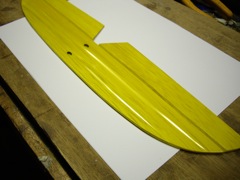
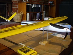
Finished Canary 7 February 2008 @ Home
This describes the first pass on building a modified version of the eHawk.
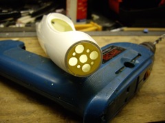
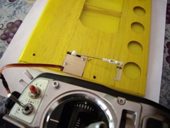
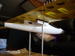
I drilled 4x8mm holes between the engine mounting holes to increase airflow. Thrust is around 800gm so the remaining fibreglass is more than adequate; unless it hits something very hard of course.
Do not be tempted to shorten the motor leads. The strands in the leads which
are the ends of the motor windings have a high temperature lacquer coating which
cannot be soldered through easily except with a high temperature iron (400C+).
Cutting these leads and then failing to make a good solder connection to all
strands in these leads will leave some windings open circuit.
I hold the motor wires down with a Velcro bridge (2 pieces with a gap between
for the wires stuck on the fuselage with a single piece bridging) so they cannot
touch the outrunner rotating magnet drum.
The tips of the folding 10x6 prop seem very soft to me and unlikely to survive one motor-on impact with anything. They do however seem very similar to the profile of thin Graupner 10x6s which I fortunately have a few of.
I am using a Hyperion Titan 20A ESC which should have enough BEC capacity for the 4xNES371 servos. I wanted to retain the option of using some 2000mAH 3s LiPo packs I have although this is clearly overkill as far as endurance is concerned. The weight penalty should not be a serious issue.
Using an eMeter with a 3s 2000mAH Hyperion LVZ LiPoly pack and the provided 10x6 propellor and 47mm hub we obtain 10.68V, 11A, 117W, 7395RPM. With an Aeronaut CAM 10x6 propellor and 42mm hub we obtain 10.72V, 11.3A,121W, 7455RPM. So the propellor is OK even if a little fragile as the tips are very soft and thin and breaking off now after only a handful of flights. The motor winding impedance seems higher than claimed. The Motocalc comparison is with the claimed 150mOhm and the apparent ~200mOhm.
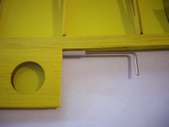
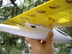
I replaced the wing mounting bolts with 4mm nylon cheese head screws and washers and did not use the brass ferrules or captive-nuts.
After I taped the wings together with masking tape I lined up the centre of
the wing up with the fuselage as accurately as possible. I then drilled one
only front wing mount hole with a 3mm bit and screwed in a 4mm nylon screw to
act as a pivot. The screw engages with the fibreglass hole in the fuselage.
I then measured the distance from each wing tip to the centre of the end of
the tail boom pivoting the wing to make these distances equal. I then drilled
the balance of the holes making sure the wing did not move relative to the fuselage.
A hint from John Bird was to put a point on the bolts using a pencil sharpener
so that the guide themsleves more readily into the holes.
I then mounted the ply wing mounting plates applying epoxy glue and then pulling
them into place with the nylon wing mounting screws. The nylon screws were coated
with petroleum jelly which prevents the Araldite gluing them in place. Tap the
holes in the ply with a 3mm tap. I applied some medium CA to the holes let it
dry then repeated the tapping process until an acceptable threaded hole was
achieved. Most nylon screws are slightly oversize assisting this process. The
Vaseline and CA thread forming tricks are also due to Prof. John Bird.
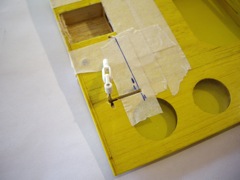
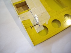
I trimmed the aileron servo section of the servo shelf off and rotated the elevator/rudder servos with the output shaft towards the front. The rear servo mounting screws can be reached through the rear wing mount holes.
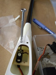
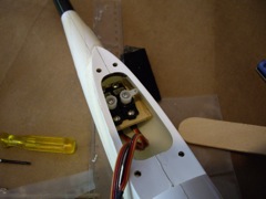
I fed the pushrods from the tail end after the tail boom was fitted using a icy-pole/mixing stick to “ramp” the rods up to the top of the servo shelf. The servos were set to neutral and the horns with rods attached were fitted to the servos leaving the ends of the pushrods protruding from the slots in the end of the tail boom. The clearances are tight and the horns I had to hand would not have cleared the fuselage sides with the servos fitted as shown in the manual.
The tail’s covering film had bubbled in several places and required re-shrinking as suggested in the manual. The rest of the tail installation was as per the manual. I intend to retain the option of removing the V clamp and flattening the tail for transport. I may add reinforcing tape to the underside of the tail to extend the life of the film “hinge”. I have some doubts as to whether the clamping screw holes will last more than a few assembly/disassembly cycles. If this is the case I will tap the clamp assembly for straight screws rather than the self-tappers.
The initial approach was to mount the spoileron servos vertically
at the wing root and use the torque rods as fitted. Unfortunately a rib under
the wing root sheeting left too little room for the servo arm between the servo
and the fuselage. This was exacerbated by the bulge outward of the fuselage
only observed after installing the servos!
I then reverted to my first choice of mounting the servos flat in the wing with
a simple cover as I did for my Coyote. This solution presents the least drag
but does involve the removal of the servo if the horn needs to be re-positioned,
which is unlikely, or if the rather fragile gear train in the NES371 servo is
damaged. There is now a metal gear kit for the NES371 which I will probably
avail myself of next time I break any gears. I will probably put a protection
fairing over the horns.
Mounting the servo flat requires the rear lugs of the servo to be removed so
it will just fit between the main spar and the sleeve of the rear wing joiner.
Fortunately the servo horn hold-down screw drops neatly into a hole in the rib
and does not bind; lucky. The distance from the root rib end face and the face
of the hidden rib is 32.5mm.
As the horn was now further outboard than when mounted vertically I cut a slot
along the line of the torque-rod and slide the sleeve outboard by approximately
1.5cm. The torque-rod tube is fortunately installed unglued hinted to in the
manual where it says it requires a small spot of Araldite to lock it in place.
With the modification to the torque rod it is of course still possible to mount
the servo vertically on the other side of the hidden rib.
The inboard torque rod slot was opened slightly to give adequate throw.
There is some backlash in the spoileron torque-rod drive which
is mainly caused by the inboard of the rod "flopping" around fore
and aft in the somewhat oversize sleeve. I at least partially cured this by
putting a drop of PVA glue on one side of the inboard end slot and then taped
the rod back against the glue until it "almost" dried. This served
to push the other side of the rod in the bottom of the slot hard against the
sleeve.
It looks a little messy after all of the chopping and changing of servo positioning
so I will probably put a layer of opaque yellow film over the out to the servo
horn and cover the servo hatch separately. As it is most of it is covered by
the fuselage anyway. I may put covers over the horns but being so far inboard
the chances of them hitting the ground and taking out the gears is pretty small.
The CA hinges were replaced with 8mm wide pinned nylon hinges on John Bird's
suggestion. I may apply film sealing to the underside of the spoilerons if leakage
becomes an issue. The standard setup unusually does not have any sealing probably
because of the torque rod mechanism.
With an intended 40% aileron differential, deploying the spoilers does not cause them to bind when using full aileron control. The torque-rod drive mechanism limits spoilers to about 45deg up which should be just enough.
While the eHawk can be flown with elevator only on the V-Tail when using a simple transmitter I certainly have rudder as well! I found with my rudderless Coyote that it was very easy to run out of directional control while landing with spoilerons up and no rudder.
Just when you think things are going extremely well along comes a minor problem. While it may be possible to balance out the aircraft with a 1200mAH pack (which I don't have) it is not so easy with a 2000mAH pack (which I do have) as the CG is 5mm too far forward! Yes I could run nose-heavy but pride does not permit; overweight yes, nose-heavy no.
So I did the following:
The NES371 servo tops are a little higher than some servos and that few millimetres is just enough to cause the horns to rub on the fuselage which is curving in onto the horns. The bottoms however were, upon inspection, 6mm off the fuselage floor! So if I was doing it again I would have taken 2mm off of each side of the mounting ply which would have dropped the NES371s to the point that the arms did not rub on the fuselage; say a millimetre clear. This will also reduce the rubbing of the pushrods against the inside top of the tail-boom. If the pushrods bind against each other, which mine did, try reversing the crossover. I also put a drop of Teflon oil on each pushrod.
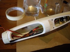
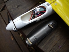
The final fuselage loading has the receiver resting on the rear of the elevator/rudder servos and the back end of the battery pack. There is zero clearance to the underside of the wing allowing for the Velcro under the battery which is lying flat in the fuselage. The antenna exits the fuselage through one of the servo slots - NOT down the "carbon" boom as specified in the Manual; why take the risk of mixing carbon, steel pushrods and 36MHz antennas. The ESC is placed on the front end of the battery and just clears the underside of the fuselage cockpit cowl.
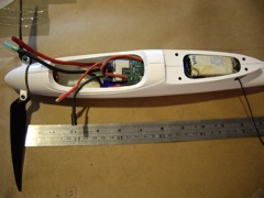
The aircraft is exactly balanced as specified.
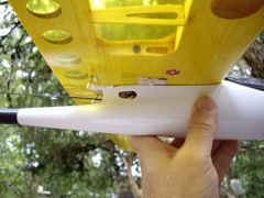
The canopy, as with Knut's build, is held on by magnet and in my case a steel washer. I simply Araldited the washer to the top of the fuselage. The canopy does sit very slightly proud of the wing. I added a locating piece of ply at the rear to prevent the canopy accidentally sliding backwards releasing the front pin. I routinely use magnets for canopies and flap closure; much less hassle.
Weight all up with the 2000mAH battery is 603gm. The static thrust is from Motocalc
slightly higher than
this although this has not been confirmed by measurement.
First flights were largely uneventful. Camber control (3mm down) and spoilerons worked well. At 40 degrees of spoiler landings are still pretty hot so I will try to increase the throw to 45/50 degrees. The ailerons do not return exactly to trim probably due to the intrinsic indirect nature of torque rods but it is acceptable. The air leakage on the hinge line without any sealing strip is hirting performance. CG although "on the spar" is clearly too far forward. The 200mAH pack is clearly over the top for endurance.
The final comment is choose Magenta NOT Yellow is it is invisible, or nearly so, against an Australian clear blue sky below about 45 degrees of elevation and 200 metres out; I plan to add some visibility and orientation aids! It is a tiny bird so that does not help visibility - should be OK on the slope closer in.
After a few hours flying I decided, in consultation with Roger Gibbs and John Bird, that some modifications to the modifications were in order and worthwhile. There is now a mini-plague of eHawks developing - at least those under construction.
Modifications include:


Copyright © G.K. & S.P. Egan - All rights reserved. Last updated March, 2016.